

In this installment, as an experiment, I am going to build the exact same box as I did in Sintra here:
Building a Sintra Box using the KRMx02
It an experiment because I will be using thin 22Ga steel. This can be problematic to cut with out some low amperage consumables and a THC.
As with the Sintra box shown here we will be cutting a top, bottom and side pieces.
The problem comes into play when we try and cut the slots for the sides.
Since the 22Ga material is only .024" thick so the grooves for the side tabs need to be the same thickness. This is not possible using the 40 Amp consumables on my Everlast plasma torch. Even with fresh consumables, the thinest kerf I can cut is about .035". Without a THC and using used consumables the best I can achieve is about .05"
There is another issue cutting thin grooves with a plasma cutter. We we do the initial piece we end up with an even larger hole. I'm getting a hole of about .09" at the pierce point.
When cutting normally we do our pierce in waste portion of the cut we are making, unfortunately we don't have enough waste in the grooves for this.
Lets give it a try anyway.
The Design
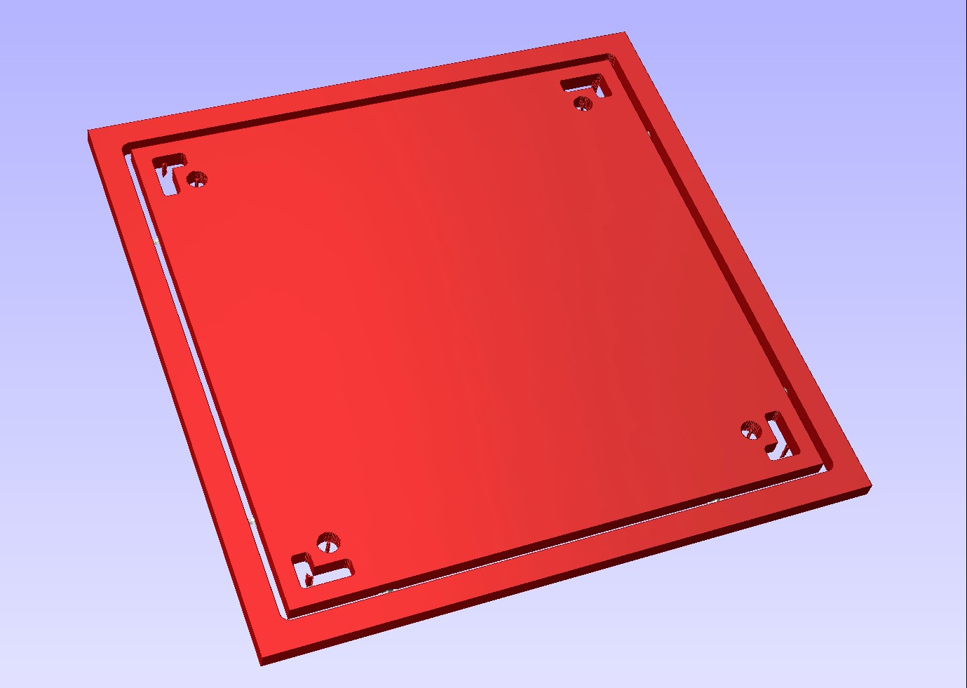
If you go back and look at the Sintra box, you will see that the steel top and bottom components are almost identical to the ones shown here.
The cut out grooves are thinner to accommodate the thinner steel I will be using.
In addition the screw holes will be pierce only holes that I will drill out later.
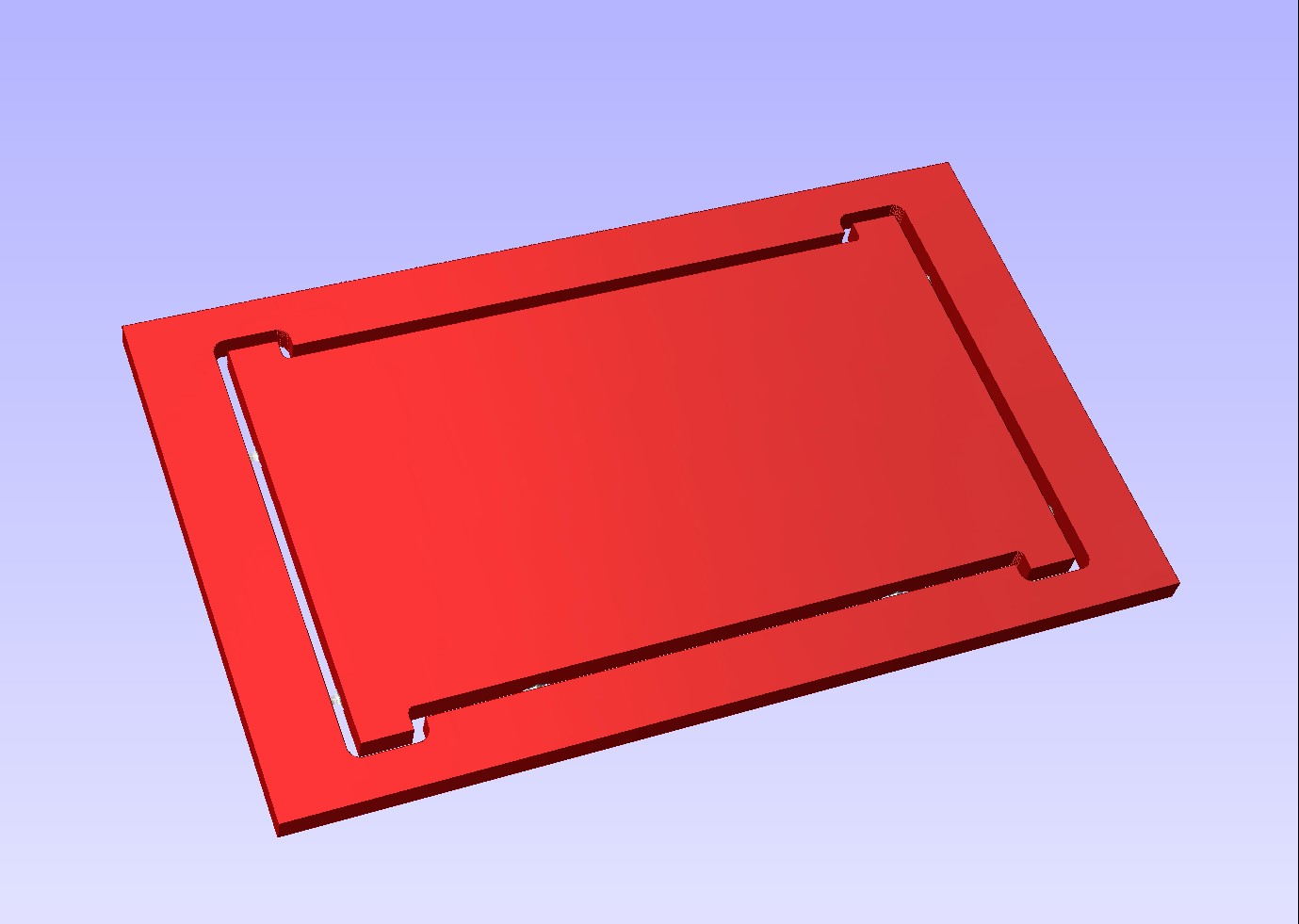
The sides are a little different as well. The tabs are smaller. This is to they come up flush with the thinner top and bottom components.
In addition, I will be adding some groves to two of the sides that will act as air vents for what ever electronics I decide to mount tin the box.
CAM
The Top/Bottom DXF is loaded into SheetCAM and the Pilot Holes, Cutouts, and profile toolpaths are created.
The same is done with the side components.
Note that when the side gcode is saved. Two different files are saved. One with the vent grooves and one without.
Cutting the Parts
First, lets take a look at the Everlast cutting the parts.
If you look close at the video, you can see that the steel warped and the torch tip was not longer at the optimum pirece and cut distance. This will drasticly effect the cut quaility and consumable life.
When cutting the top will have the best finish. Take a look at the grooves we cut for the side panels.
I set the pierce point to be in the corner of the grooves. You can see the large hole created by the pierce operation.
Another thing to notice is that the pilot pierce in the upper right corner seems to be smaller and more uniform. This is because the torch has no pressure so it only actually fired for about half the pierce duration. The other holes are larger and have more dross.
I think a blank fire before starting the pierce may solve this issue and allow me to lower the over all pierce delay and create smaller pilot holes.
The bottom side of the part will have more dross as seen here.
This dross will have to be cleaned off. The dross on the edges can be scrapped off, but the dross arround the corners on on features will need to be flap sanded.
Here the features have been cleaned with a flap sander. My next step will be to drill the pilot pierces with a .149" drill bit so that I can insert a #6-32 machine screw.
When cutting the vent grooves the torch actually came in contact with the steel (due to warpage). As a result the cut quality was horrible and the pierce holes were so large they removed too much of the stock.
This problem can be solved with a THC (Torch Height Control).
Even an IHS (Inital Height Sensor) will help.
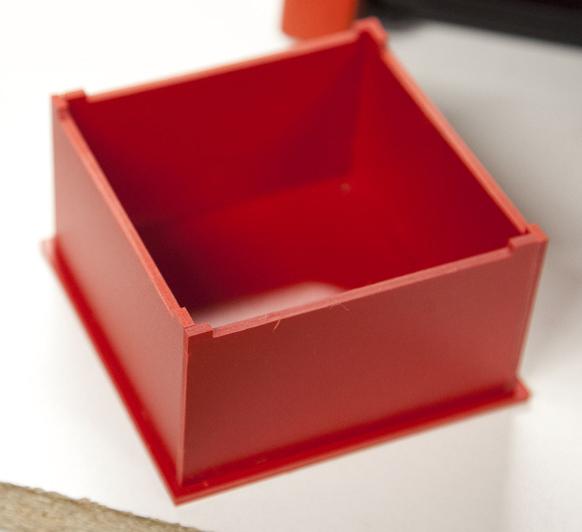
Assembly
The side component tabs are placed into the groves on the top component.
Notice how I used some small magnets to hold the sides in place.
You can also use tape to hold the sides in place as you assemble.
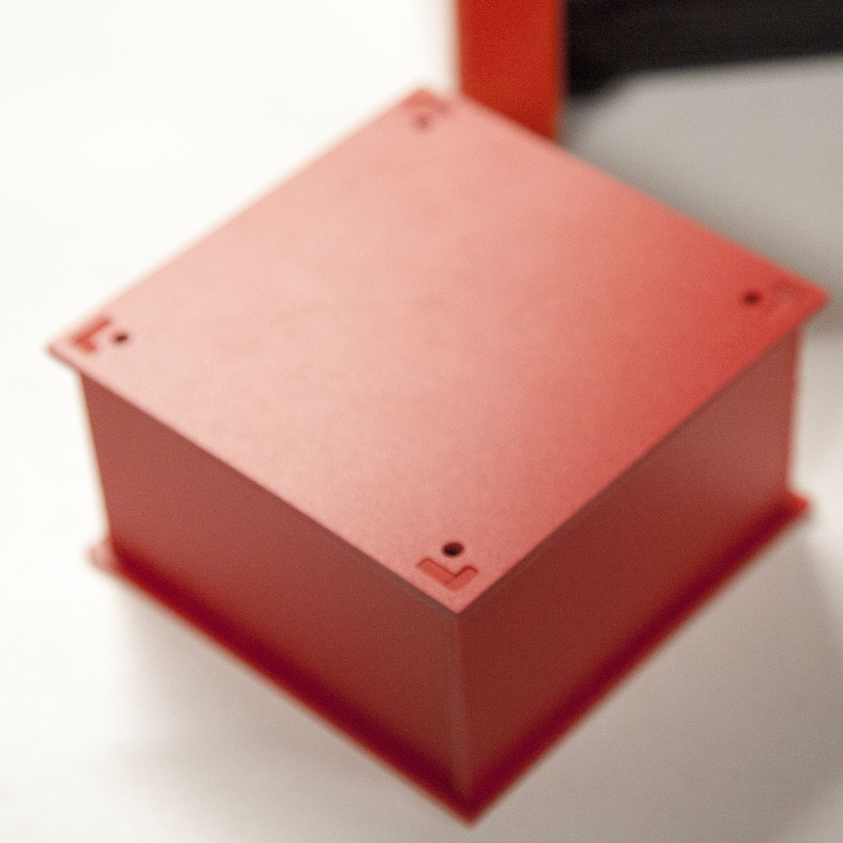
Place the bottom component over the tabs and secure with some screws.
Here I cut off the excess screw.
I then remove the nuts and add acorn nuts.
Conclusion
I was very surprised at the rigidity of this box.
You can add other features to the sides to support knobs and switches as needed.
You can also weld or braze the sides so that they are easy to dissassemble/assemble as needed.
The corners can be very sharp on steel projects. Make sure your round them a little.
Note that you can use some 220 grit sand paper to clean up the components before assembly. I decided to keep the rough look for this box.
All in all this steel box is serviceable and can be drastically improved by changing to lower amperage consumables, and by adding a THC and/or a IHS.
Moving to a thicker guage material would:
- Result in less warpage
- Allow the tab grooves in the top and bottom components to be larger
In closing I want to add that I have some 20Amp consumables on the way. I will also be installing a THC and IHS in the next day or two. Once complete, I will try this box again.