

The HY02D223B Type 2 as I call it, is sometimes referred to as the Clone HY02D223B Inverter. It most likely is a simpler copy of the original HY02D223B, but dont discount just yet. While it does not have a Modbus interface it is very easy to hookup and control with Mach3.
Important - Please note that I no longer use this (Type 2) VFD. I have moved all my spindles to the Type 1. For this reason, I will not longer be updating any information for this (Type 2) VFD, as I no longer own one. IE what you see is what you get.
I ordered this VFD along with a 2.2Kw spindle from Amazon here:
Water Cooled 2.2Kw Spindle and VFD
You can also get one without the spindle here:
Note that I could not find any 2.2Kw 80mm Air cooled spindle combos with this VFD. If you want this VFD with an air cooled spindle you will need to purchase them separately.
The air cooled spindle can be found here:
Important ……..
This VFD is permantly set to 220V output at the spindle. This means you can’t drive a 110v 3 phase spindle.
Power the VFD
We need to get some power to your VFD so that you can edit some of the parameters.
Power Cord
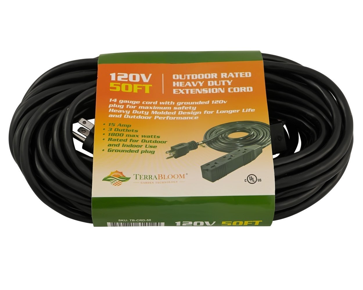
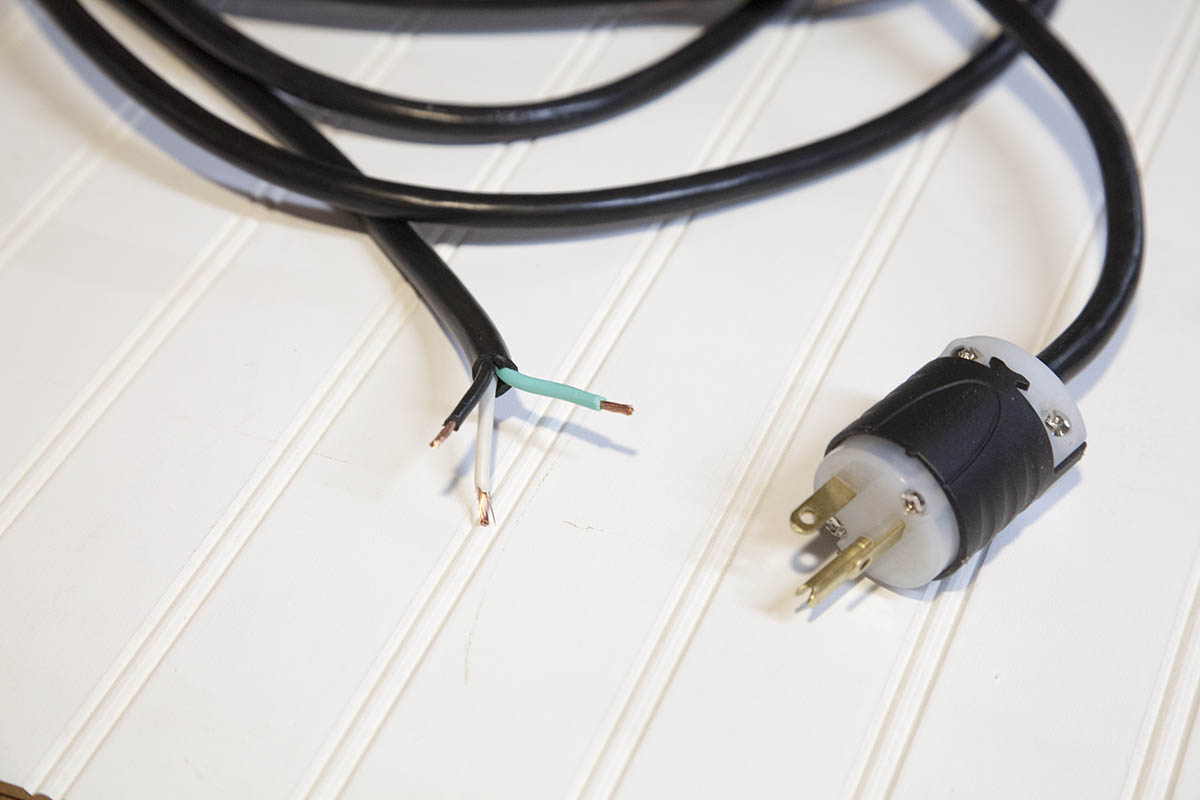
To start you will need to make a power cord. Since you will also need a cord for your spindle, it's best to purchase a 50' 14guage extension cord and cut the ends off.
Cut the cord in half and use one half to make your VFD power cord and the other to make your spindle cord.
You will need a power plug to match your shop power outlets.
You can pickup an extension cord here:
Connecting Cord to VFD
This controller can be powered by three phase or single phase. To connect to a 220v single phase you connect the other end of the power cord to the terminals shown here.
Black and white leads connect to R and T terminals. Green is connected to the ground shown here.
Plug-in the Power Cord
Re-check your connections, then plug the power cord into the 220v outlet.
After a second or two you should see your VFD come to life. Once the unit boots, you will be presented with a display that looks something like this. Don't be concerned about the actual display contents at this point as it may differ from mine.
Setting Parameters
Before moving forward, you need to make sure some of the parameters are setup properly before connecting the spindle. Failure to do so could burn up your spindle.
How to Edit a Parameter
To edit one or more parameters, start by hitting the SET button. You will be presented with a Pn xx display like the one shown here.
You change the actual parameter number you want to edit by using the up/down arrows. Here I changed the parameter number to Pn 02.
Note that you can use the JOG buttons to move the digit you will be affecting with the arrow keys.
To edit a parameter hit the SET button. You will be presented with the value of the parameter you selected. In this case, parameter Pn 02 has a value of 400.00 as shown here.
To change the value, use the up/down arrows. Remember you can use the JOG buttons to change the digit you want to edit.
To apply the new value, hit the SET button again. The new value will be saved and you will be taken to the next parameter. In this case, we moved to parameter Pn 03.
Initial Parameters
Change the following parameters before proceding.
Pn 01=24000
Pn 02=400
Pn 03=2
Pn 04=1
Pn 12=400
Connecting the Spindle
Take the other half of the power cord and strip the insulation from both ends as shown here.
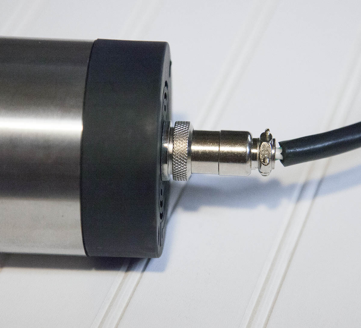
Disassemble the connector that came with the spindle and slip the sleeve over the cable as shown.
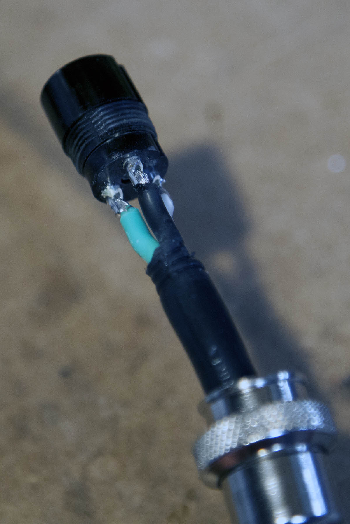
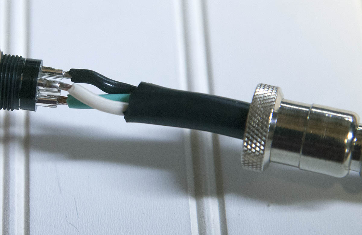
If the spindle has a four pin interface, solder the three wires to pins 1,2, and 3.
If the spindle has a 3 three pin interface, solder the three wires to each of the pins.
If your spindle has 4 pins, ignore pin 4 as it is spindle ground and wont be used.
Re-assemble the connector and attach to the spindle as shown here.
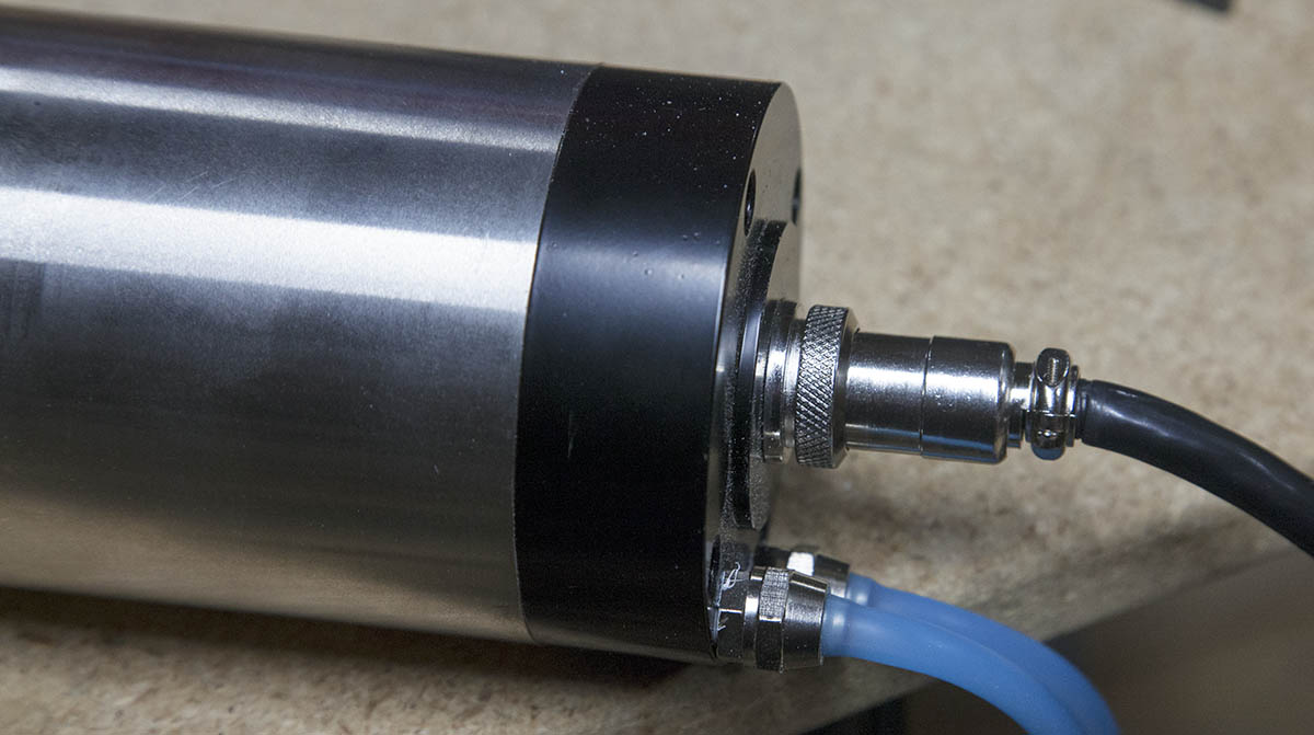
Attach the other end of the cable to the terminals marked U, V, and W as shown here.
Connecting a Potentiometer to the VFD
When all is said and done, you probably wont be using the potentiometer on your VFD once you can control the speed with Mach3. I feel this is an important step, It will ease the transition to full automation.
You will need a 5 or 10K potentiometer, you can pick one here:
Attach three wires to the POT, as shown here.
Connect the wire connected to the center lug on the POT, to the terminal labeled 5VIN on the VFD.
Connect a wire connected to an end lug on the POT to the terminal labeled GND on the VFD.
Connect the remaining lead from on the POT to the terminal labeled 5VOUT on the VFD.
Setting VFD Parameters for a Potentiometer.
In order for the potentiometer to work, you need to make the following parameter changes.
Pn 03=3 (External 5V)
Testing the Potentiometer
On this VFD, setting the speed of the spindle is easy. The display always shows the value to be set in spindle RPMs. Just dial in the RPMs you want with the potentiomiter and hit the run button.
Starting and Stopping the VFD with Mach3
In order to turn the spindle on and off, you need to setup and output on your controller. Some controllers have a built-in output relay that can be used.
In my case I am using a GeckoDrive G540 controller. It has two outputs called Output1 and Output2. These can be used to drive a relay that can control things. The G540 can drive the VFD directly by connecting GND and Output1 to the VFD.
In my case I am using a GeckoDrive G540 controller. The G540 can drive the VFD directly by connecting GND and Output1 to the VFD.
Connect the GND lead (G540 GND) to the GND position on the terminal block shown here (green wire).
Connect the Output lead (G540 Output1) to the FWD position on the terminal block (white wire).
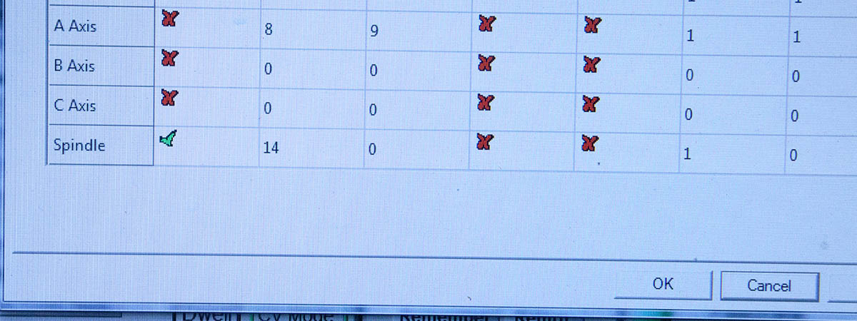
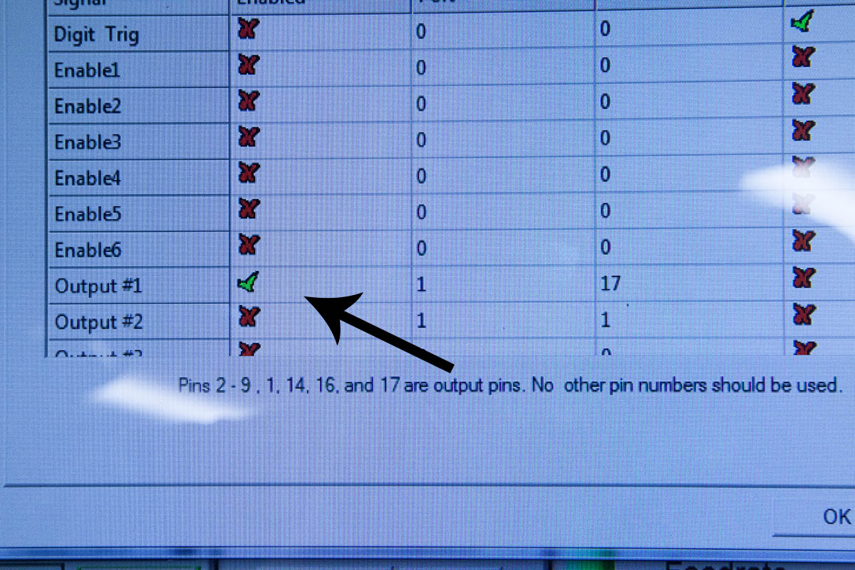
Note that you will need to configure Mach3 in both the spindle section and the output pins to point to Output 1 on the G540.
I will cover the actual configuration in more detail in the final workbook.
See below for some configuration screenshots.
Setting VFD Parameters for Remote Start
In order for Mach3 to turn the spindle on and off, you need to make the following parameter changes.
Pn 04=2 (External signal control)
Testing the External Trigger
By clicking the spindle control button on the main Mach3 screen, you can toggle the spindle on and off.
Controlling Spindle Speed with Mach3
Using Mach3 to control the spindle speed using this VFD is very easy. You will replace the potentiometer with three leads from the G540.
Wiring
Connect three wires to the G540 as shown here:
In this case:
Black = VFD Ground (G540 Pos 7)
Yellow = VFD Output (G540 Pos 8)
Red = VFD +10VDC (G540 Pos 9)
Attach the red lead (VFD +10vdc) to the 5v out position on the terminal block as shown here.
Attach the black lead (VFD Ground) to the GND out position on the terminal block as shown here.
Attach the yellow lead (VFD Output) to the 5v IN position on the terminal block as shown here.
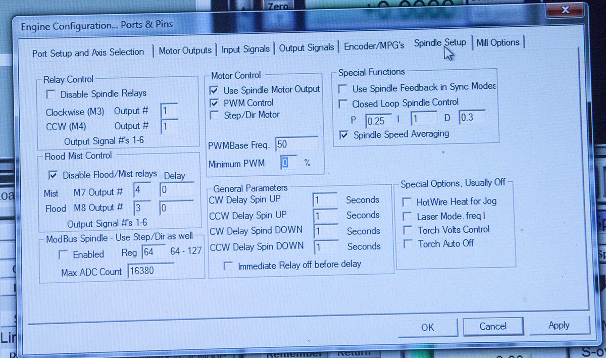
Mach3 Configuration
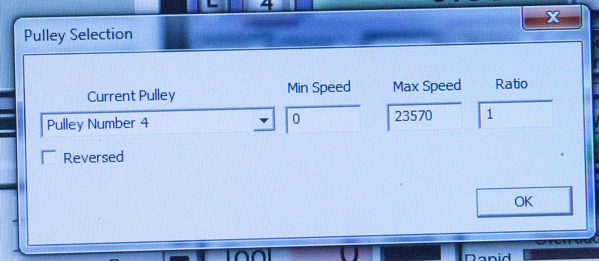
You will need to make the configuration changes shown here in order for Mach3 to change the speed of the spindle.
Note that these are for a G540 connected to the VFD.
Use the pulley settings to dial-in the PWM signal sent to the VFD.
As stated before, I will be going into more detail in the actual workbook, but these settings should get you started.
VFD Configuration
Be sure your VFD has the following parameters set:
Pn 01=24000
Pn 02=400
Pn 03=3
Pn 04=2
Pn 12=400
Testing Mach3 Spindle Speed Control
By clicking the spindle control button on the main Mach3 screen, you can toggle the spindle on and off.
You can change the spindle speed by using the up and down arrows on the Spindle Speed Pane shown here.
You can also type the speed directly into the Spindle Speed field.
The VFD will display the spindle speed within a few RPMs as shown here.
This particular VFD is the simplest VFD I have ever interfaced to Mach3. The interface to the G540 controller is what makes it so easy. While this VFD does not support a Modbus interface, I found that it was not needed. Note that other controllers may not be so easy, especially those that dont have a PWM output.
If you cant get your Mach3 speed to match the speed shown on the VFD ROT display, try deleting the file called linearity.dat in the Mach3/macros/KRMx02 directory. When you restart Mach3, it will create a new linearity.dat file with a 1 to 1 speed curve.
Breaking Resistor
Please note that this VFD does not support a breaking resistor. While the manual indicates that it does, and even includes registers for setting it up. There is no circuitry to support it.
If for some reason you need a breaking resistor, you will need to look for another VFD.